
Gas Well Deliquification: Plunger Lift Part-I
- Oct 19, 2016
- 3 min read
As you are aware, we are in the process of writing our blog series on gas well deliquification technologies currently being used by operators around the globe to handle their water production problems. This blog is targeted towards describing one of the most unique artificial lift system called Plunger Lift.
Plunger lift is a well-known and widely used technique to dewater gas wells. It utilizes wells own energy which is stored in the casing-tubing annulus while well is shut-in to push a plunger and the accumulated liquid column on top of the plunger upwards to remove water from the wellbore.
Plunger lift is composed of few basic parts of equipment, mainly divided between surface & downhole equipment. Surface equipment includes control valves, lubricator, electronics & plunger catching/holding assembly. Downhole setup includes casing/tubing valve and spring. Ofcourse, the plunger itself is the element that moves up & down the wellbore between the downhole spring and top catching assembly. Following diagram outlines the different parts of plunger lift.
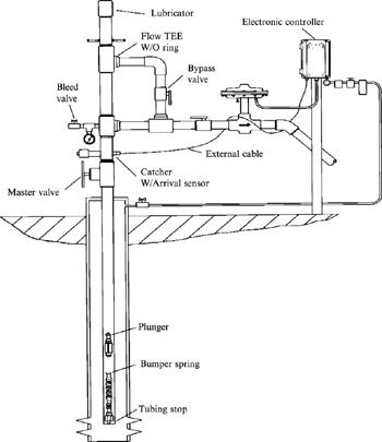
Figure outlining different parts of Plunger lift. Reference: IEEE GlobalSpec
Moving plunger up & down inside the tubing provides a mechanical interface between the produced liquids and gas. Operation of the plunger system relies on the natural buildup of pressure in a gas well while the well is shut-in. The shut-in pressure of the well must be higher than the sales-line pressure to move plunger.
Following conditions are favorable for plunger lift to work optimally:
Gas Liquid Ratio (GLR) play an important role in plunger lift efficiency, GLR should approximately 400 scf/bbls per 1000 ft. of depth.
Pressure build-up by flow and no-flow periods are essential for conventional plunger to work.
Uniform tubing size and wellhead configuration are must, tubing must not have any side pocket manderals or profiling etc.
No Sand production in the well (as sand hold up and flow can cause mechanical restiriction to the movement of plunger)
Before plungers are installed, running a gauge cutter and/or scrapper is a good practice to check and ensure clearance of wellbore.
Working of conventional plunger lift system:
Plunger lift system works in two cycles- Closed Cycle and Open Cycle:
Closed Cycle: Well is static, plunger falls down on the liquid column and rests on the downhole spring.
Open Cycle: The accumulated gas pushes the plunger and liquid column in upward direction, the removal of liquid column lowers bottom hole pressure of the well and allows gas from the reservoir to flow.
Detailed working steps of plunger lift are as follows:
Well is flowing, producing water & gas. With time, water starts to hold up in wellbore but hydrostatic head is still less than reservoir pressure and gas is produced. Plunger hangs at the well head in open position due to gas flow.
Soon the hold-up of water in wellbore is adequate to have enough hydrostatic head that ceases flow from the formation.
Well is automatically shut-in at the well head, plunger falls down and closes. Short build up period starts.
The well is opened, built pressure inside the well assist plunger in closed posture to travel upwards with liquid column.
Plunger receives at the surface. Water is produced out and with decrease in hydrostatic head well starts to flow again while holding plunger at the wellhead.
As flow is restored, water starts to hold up again in wellbore and cycle is repeated.
Following animation by Ferguson Beauregard on their youtube channel outline the basic working steps of plunger lift.
Certain calculations are must to evaluate and design a plunger lift for any candidate well. Although several factors are reviewed, one of the most important one is build-up time. All plunger lift wells are in essence intermittent producers or cyclic producers, and they have downtime where pressure is built inside the well to lift the plunger and water column to surface. Although optimum wells for plunger lift have this cycle many times in 24 hours, it nevertheless has downtime.
In the second part of this plunger lift blog, we will describe how a well is screened and selected for this artificial lift technology, and what design elements are considered. We will also walkthrough some of the vertical lift performance models used in the industry to model wells with plunger lift.
If you like this blog, kindly comment and share.


Comments